Home> Company News> Pressure distribution in journal bearing
- Address4 Pemimpin Drive #03-09, Lip Hing Wholesalers Industrial Building Singapore 576147
- Factory Address1589 Tampines Industrial Wholesalers Avenue 5 Singapore 528759
- WorktimeЗ понеділка по п'ятницю: з 9:00 до 18:00
- Phone(Working Time)00(65) 6258 1688
The trainer covers a wide range of topics in mechanical vibration technology. It is mounted on a sturdy, low-vibration frame which is installed on a laboratory trolley with braked wheels. Quick fastening elements for the formed grooves for quick and accurate experimental set-up. Forced vibration is generated with an electrical motor-driven imbalance exciter. The exciter frequency can be set precisely on a control unit with digital display. An oil damper is used for vibration abatement. A bar-type oscillator that can be adjusted with weights is included for absorber experiments. A mechanical drum and a polar diagram recorder record the vibration. Instructional and experimental vibration system, experiments on damping, resonance, two-weight system and vibration absorption 6 pendulum oscillators, 2 bar-type oscillators, 1 spring mass oscillator electrical imbalance exciter electronic exciter control unit with digital frequency display and TTL output for triggering external units adjustable absorber with leaf spring oil-filled damper. Techical Data : 'Bar, rigid: LxWxH: 700x25x12mm, 1,6kg; Bar, flexible: LxWxH: 25x4x700mm, 0,6kg; Tension / compression springs : 0,75N/mm; 1,5N/mm; 3,0N/mm; Imbalance exciter : 0...50Hz; 100cmg; Oil-filled damper: 5...15Ns/m; Absorber : leaf spring (wxh: 20x1,5mm), total weight: approx. 1,1kg, adjustable 5...50Hz; Groove width of frame: 10mm; Drum recorder: 20mm/s, width 100mm; Polar diagram recorder: D=100mm; Included : Software for Data Acquisition with Technical Description : This data acquisition system is specially designed to evaluate the vibration signals on a PC. This system makes it easy to generate, store and print out frequency and phase response curves. The system provides the important functions of a digital storage oscilloscope and can calculate the frequency spectrums of the signals. The core of the system is the interface box. It supplies power to up to three sensors and processes the measured signals for the PC. It also displays the signals on three analog outputs.
In hydrodynamic journal bearings the shaft and the bearing shell are separated from each other during operation by a lubricating film. The supporting function of the lubricating film in the journal bearing can be described by the pressure distribution in the bearing gap. This unit is used to visualise the axial and radial pressure profile in the journal bearing with hydrodynamic lubrication. To do this, there are 12 measuring points around the circumference of the bearing shell and 4 measuring points in the longitudinal direction. The respective pressures can be read via 16 tube manometers with reference to the height of the liquid column. The journal bearing consists of an electrically driven journal that rotates in a freely movable bearing housing. Oil is used as the lubricant. The displacement of the shaft journal depending on the speed and direction of rotation as well as the characteristic behaviour during start-up can be observed through the transparent bearing housing. Speed and direction can be adjusted. The load can be adjusted by varying the weights supplied with the unit. The temperature in the bearing gap is measured in order to determine the viscosity of the lubricant. Specification : Visualization and investigation of pressure distribution in journal bearings, Bearing housing is completely transparent, Bearing housing moves freely on the rotating journal Infinitely variable speed, electronically controlled, Load on the bearing via set of weight included with the unit, Temperature measurement in the bearing housing radial and axial pressure distribution indicated with 16 tube manometers, Digital display for speed on the display and control unit.
Technical Data :
Bearing : nominal bearing diameter: 51mm, bearing gap: 4mm, bearing width: 75mm, bearing load: 6,7...16,7N; Motor : power: 0,37kW, max. speed: 3000min; Oil ISO viscosity grade: VG 32; Tank for oil: 2,5L; Set of weights : 1x 1N (hanger), 2x 2N, 1x 5N; Measuring ranges : pressure: 1770mm oil column, temperature: -10...50°C, speed: 0...3000min
New Products
Deep Groove Ball Bearings Angular Contact Ball Bearings Self-Aligning Ball Bearings Thrust Ball Bearings Cylindrical Roller Bearings Needle Roller Bearings Tapered Roller Bearings Spherical Roller Bearings Cylindrical Roller Thrust Bearings Needle Roller Thrust Bearings Spherical Roller Thrust Bearings Sumitomo Cam Rollers Concrete Mixer Truck Bearings Cam followers Spherical Plain Bearings Rod Ends Wheel Hubs Constant Velocity Joints Piston Pumps Solenoid Directional Valves Fans Cooling Piston Motors Belt Drives Chain Drives Gears Rack SKF Bearing in Indonesia Rail Products Round Profile and Square Electric Motors Siemens Supply O-rings and V-rings Slewing Rings Mold Plain-Bearing Bushings Rexroth 2frm Ball and Roller Screws Oil Seals Singapore Retaining Rings V-Rings Rexroth a8vo Vickers Steam Turbine Pump Daikin Positive Displacement Pump Yuken Impeller Pump SKF Bearings SKF Bearing Units SKF Bearing Accessories SKF Bearing Shaft Seals SKF Bearing Housing FAG Bearings Germany Timken Bearings Oilfield Equipment Bearings Mud Pump Crankshaft Bearing NSK Bearings FAG Bearings KOYO Bearing Germany Bearing Loyal Bearing Germany ABB USA Bearings Germany Bearings Oilfield Bearings Rolling Bearings Japan Bearings Thin Section Bearings Double Row Tapered Roller Bearings (Inch Series) Four-Row Cylindrical Roller Bearing Inner Ring Outer Assembly Thrust Spherical Roller Bearing Screwdown Systems Thrust Tapered RollEr Bearings Multi-Row Roller Bearings NTN Four Row Cylindrical Roller Bearings NTN SL Type Cylindrical Roller Bearings NTN SL Type Cylindrical Roller Bearings for Sheaves NTN Single Row Tapered Roller Bearings NTN Double Row Tapered Roller Bearings NTN Four Row Tapered Roller Bearings NTN Spherical Roller Bearings NTN Thrust Bearings NTN Double-Row Cylindrical Roller Bearings NSK Bearings For Special Applications NTN Full-Complement Cylindrical Roller Bearings NSK Single-Row Tapered Roller Bearings NSK YUKEN Piston Pump Double-Row Tapered Roller Bearings NSK Spherical Roller Bearings NSK Single-Direction Thrust Ball Bearings NSK Cylindrical Roller Thrust Bearings NSK Tapered Roller Thrust Bearings NSK Spherical Thrust Roller Bearings NSK Rolling Bearings For Steel Mills NSK Sealed-Clean Four-Row Tapered Roller Bearings NSK Four-Row Cylindrical Roller Bearings NSK Double-Row Tapered Roller Bearings NSK Roll Bearings For Mills NSK Crossed-Roller Bearings NSK Ball Bearings NSK Tapered Roller Thrust Bearings For Adjusting Screws NSK Roller Bearings NSK Thin Section Bearings Kaydon Double Row Double Row Tapered Roller Bearings (Inch Series) Full Complement Tapered Roller Thrust Bearing Thrust Cylindrical Roller Bearings Thrust Spherical Roller Bearings Sealed Four Row Tapered Roller Bearings Four Row Tapered Roller Bearings Double Outer Double Row Tapered Roller Bearings Tdo Double-Row Tapered Roller Bearings Single Row Tapered Roller Bearings Inch Double Inner Double Row Tapered Roller Bearings Tdi Single Row Tapered Roller Bearings Double Inner Double Row Tapered Roller Bearings Inch Split Spherical Roller Bearings Spherical Roller Bearing Four Row Cylindrical Roller Bearings Single Row Cylindrical Roller Bearings Full Row Of Cylindrical Roller Bearings Double Row Cylindrical Roller Bearings Double Row Full Complement Cylindrical Roller Bearings Four Point Contact Ball Bearings Double Row Angular Contact Ball Bearings Deep Groove Ball Bearings Angular Contact Thrust Ball Bearings Type TVL DTVL Angular Contact Thrust Ball Bearing TP Thrust Cylindrical Roller Bearing TPS Thrust Cylindrical Roller Bearing Thrust Spherical Roller Bearings Types TSR-EJ And TSR-EM TTHD Thrust Tapered Roller Bearings TTHDFL Thrust Tapered Roller Bearing TTHDFLSA Thrust Tapered Roller Bearings THRUST Tapered Roller Bearings Types TTSP, TTSPS AND TTSPL Thrust Tapered Roller Bearings–TYPES TTC, TTCS AND TTCL Screwdown Bearings–Types TTHDSX/SV And TTHDFLSX/SV Thrust Tapered Roller Bearing Types TTDWK And TTDFLK Crossed Roller Bearings TXR Tapered Roller Bearings Double-Row•Type TDO Tapered Roller Bearings Double-Row TDI TDIT Tapered Roller Bearings Double-Row TNA Tapered Roller Bearings Double-Row TNASWE Tapered Roller Bearings Double-Row Spacer Assemblies TTVS TTSP TTC TTCS TTCL Tapered Roller Thrust Bearings Heavy-Duty Shaker Screen Spherical Roller Bearings Timken Spherical Roller Bearings Cylindrical Roller Bearings One-Row Metric ISO Series Cylindrical Roller Bearings One-Row Standard Series Cylindrical Roller Bearings Full-Complement NCF Cylindrical Roller Bearings Two-Row Four-Row Cylindrical Roller Bearings Cylindrical Roller Bearings HJ Series Cylindrical Roller Bearings 5200 A5200 Metric Series Heavy-Duty Needle Roller Bearings Four-Row Cylindrical Roller Bearing Assembly Four-Row Cylindrical Roller Bearing Inner Ring Outer Assembly Four-Row Tapered Roller Bearings•Tqow–2TDIW Timken Sealed Roll Neck Bearings Four-Row Tapered Roller Bearings TQITS Tnaswh Two-Row Tapered Roller Bearings Tdit Tnat Two-Row Tapered Roller Bearings Tdik Thrust Tapered Roller Bearings Ttdflk Ttdw And Ttdk Bearings Screwdown Systems Thrust Tapered Roller Bearings Thrust Spherical Roller Bearing TOKYO-KEIKI Vane Pump YUKEN Vane Pump DAIKIN Piston Pump DAIKIN Rotor pump Vickers Vane Pump VICKERS Gear Pump NACHI Gear Pump NACHI Piston Pump Rexroth A1VO Rexroth A10VSO Rexroth AA4VSO Rexroth A15VSO Rexroth AZPF parker PV piston pump parker PVP piston pump Parker PAVC Piston Pump Parker Vane Pump Main Pump


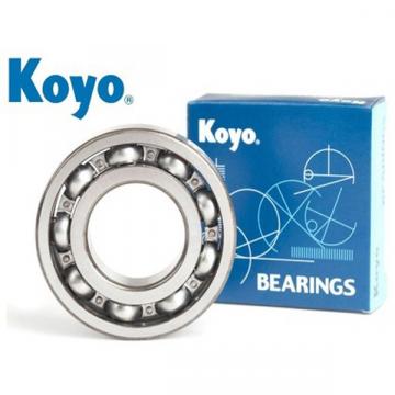 KOYO Bearing Distributor in Singapore
 MCGILL Distributor in Singapore
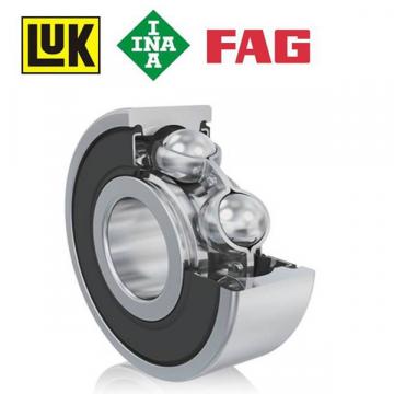 FAG & INA Bearing Distributor in Singapore
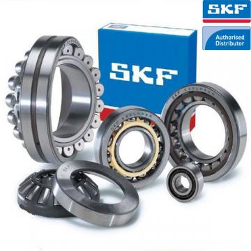 SKF Bearing Distributor in Singapore
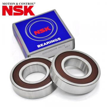 NSK Bearing Distributor in Singapore